When debugging electromagnetic navigation modules, developers often encounter a difficult problem. Although the circuit is designed according to theory, the measured signals are full of unexplainable noise, which has a serious impact on navigation accuracy.

Preliminary investigation of noise phenomena
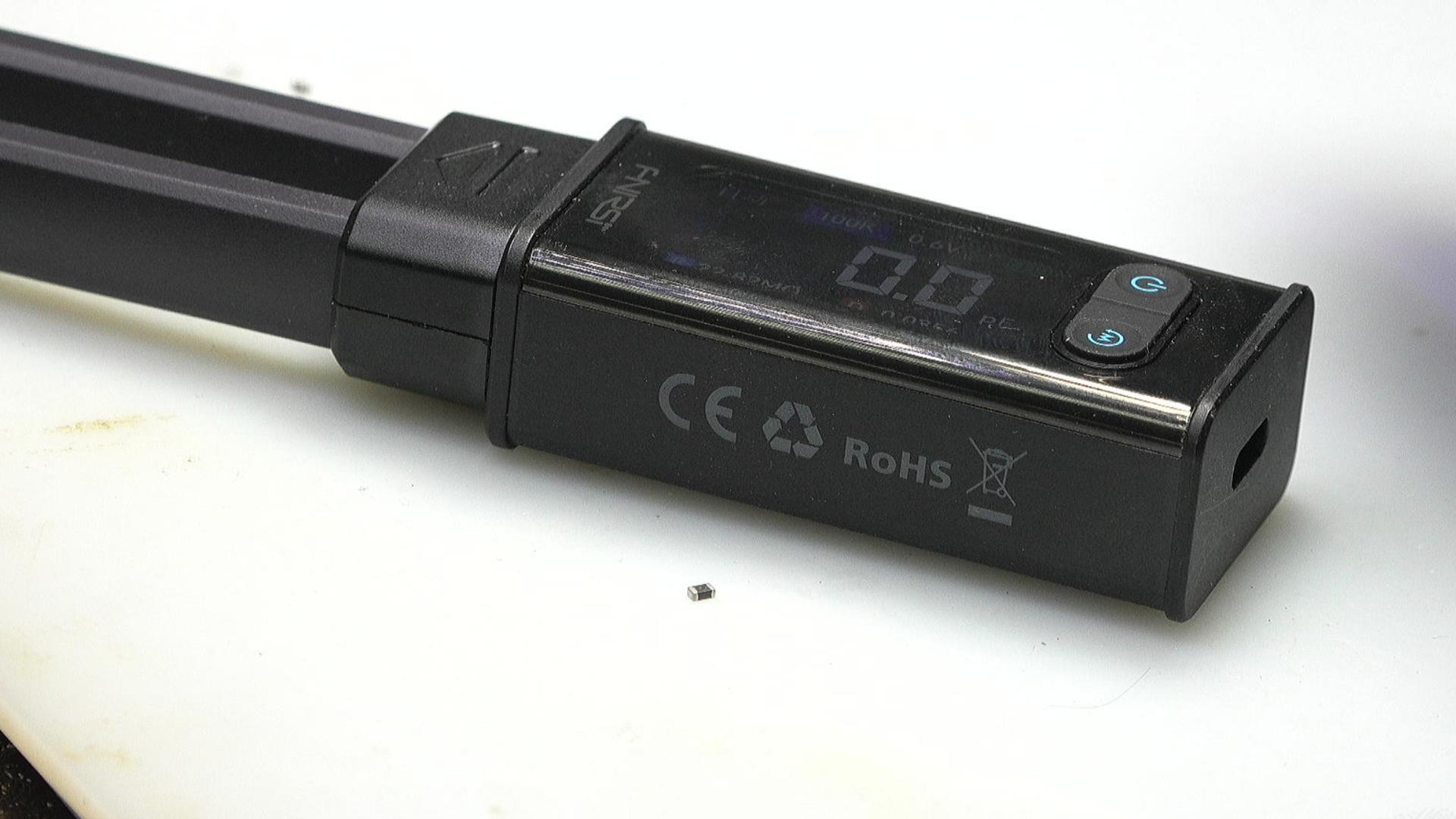
Initially, an LCR meter was used to measure the receiving inductance of the module. The readings were around 700 nanohenries and 150 milliohms, indicating instability. Using the more convenient LCR tweezers, there is no way to measure this component. This conveys that conventional inspection tools may not be able to accurately capture the characteristics of a component in operation, especially when it is integrated into a complex circuit.
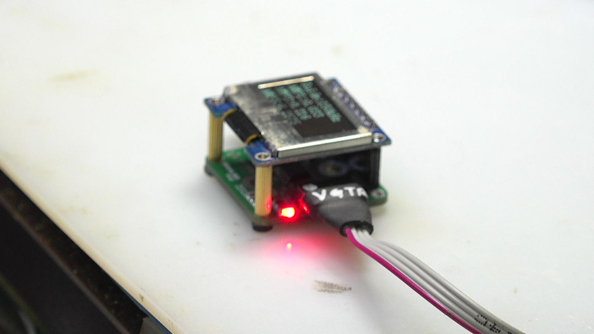
A nominal 1mH inductor is used as the receiving antenna. This is the method used by the module itself. Tests have confirmed that there are large random fluctuations in its output measurement signal, which directly makes the navigation data unreliable and becomes a core technical obstacle that must be solved.
First hypothesis on high frequency interference
In view of the common presence of 2.4GHz signals such as WiFi in the module working environment, engineers initially suspected that these high-frequency wireless signals had interfered with the circuit. Theoretical speculation is that the inductor used as an antenna absorbs high-frequency noise in the environment and couples into the first-stage operational amplifier, thereby contaminating the useful signal.
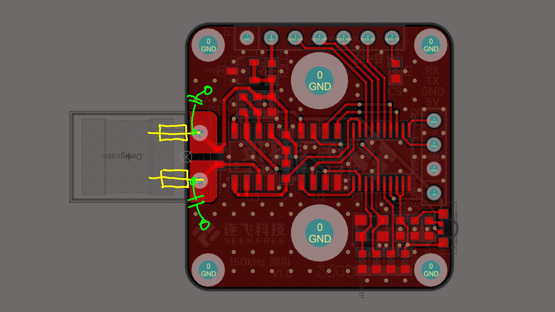
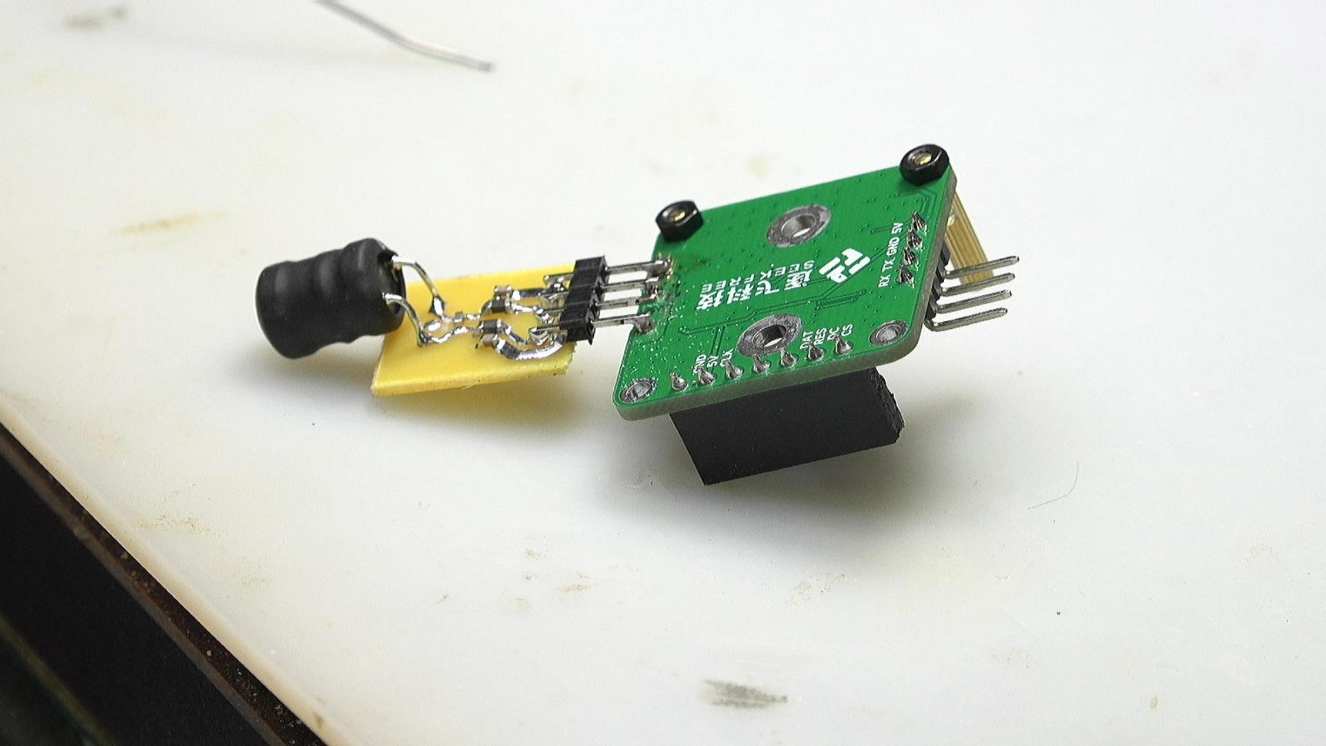
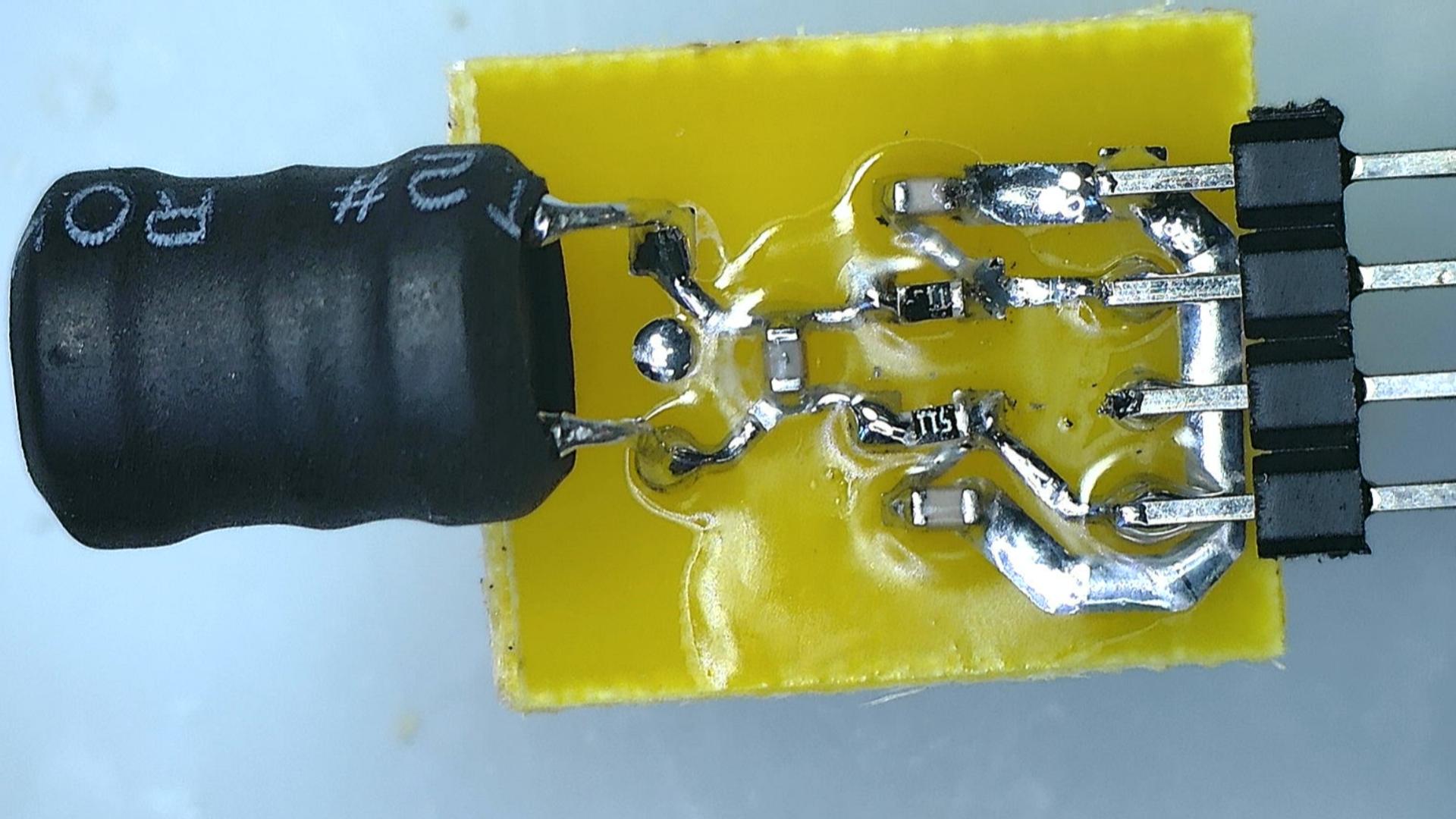
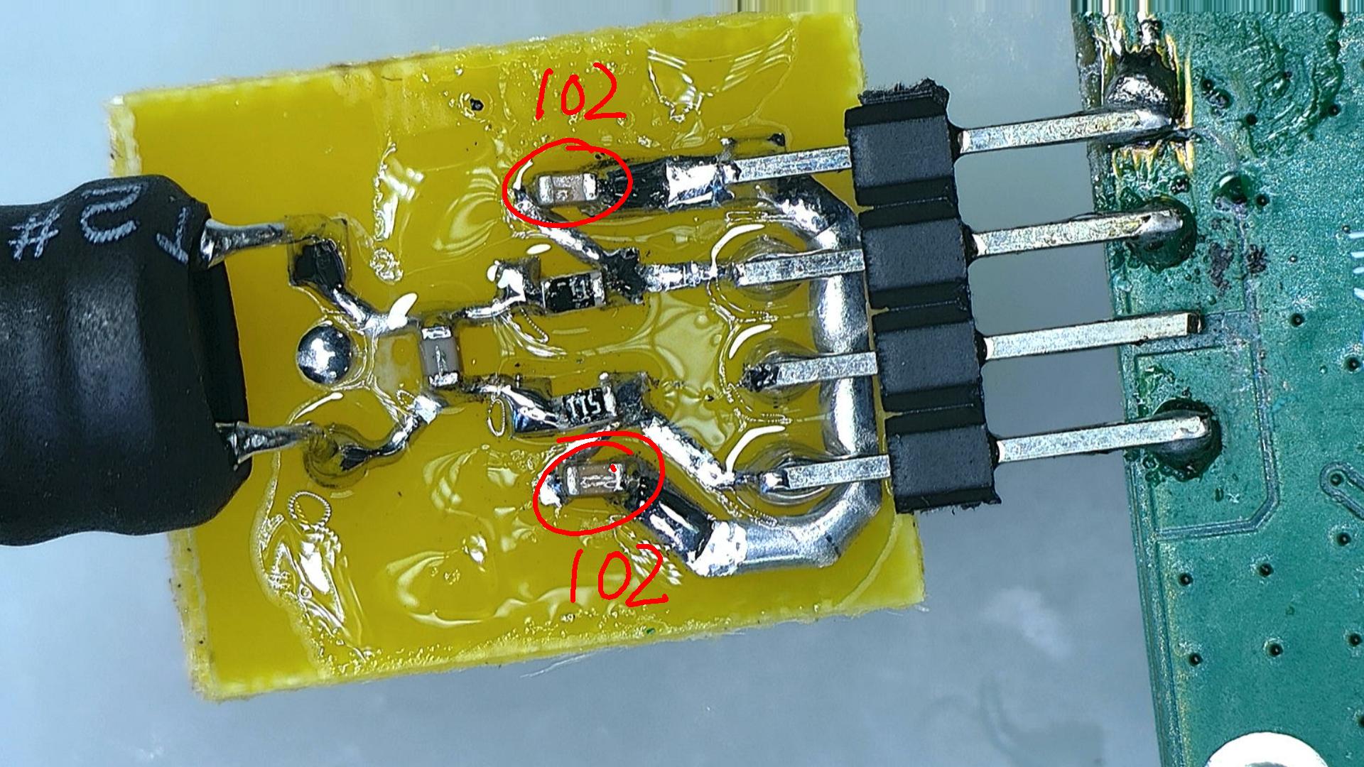
Based on this assumption, the team conceived and designed a filtering solution. Specifically, the external inductor must first pass through a magnetic bead, which is a high-frequency loss component, and then connected to the circuit board. At the same time, a high-frequency capacitor is connected in parallel at the node position before the signal enters the circuit. The purpose is to try to introduce the interference signal to the ground in advance.
Verification of the first filtering scheme
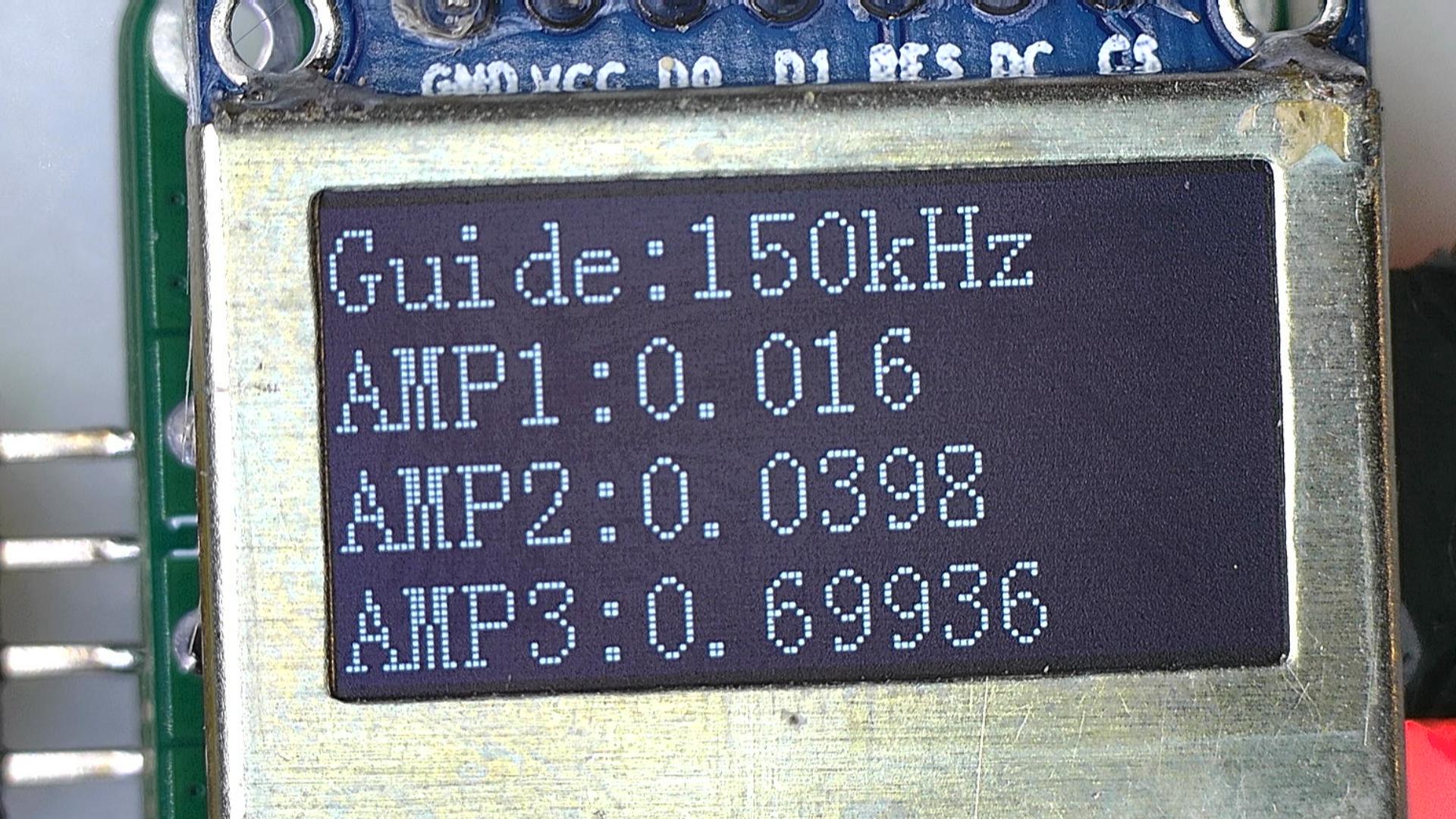
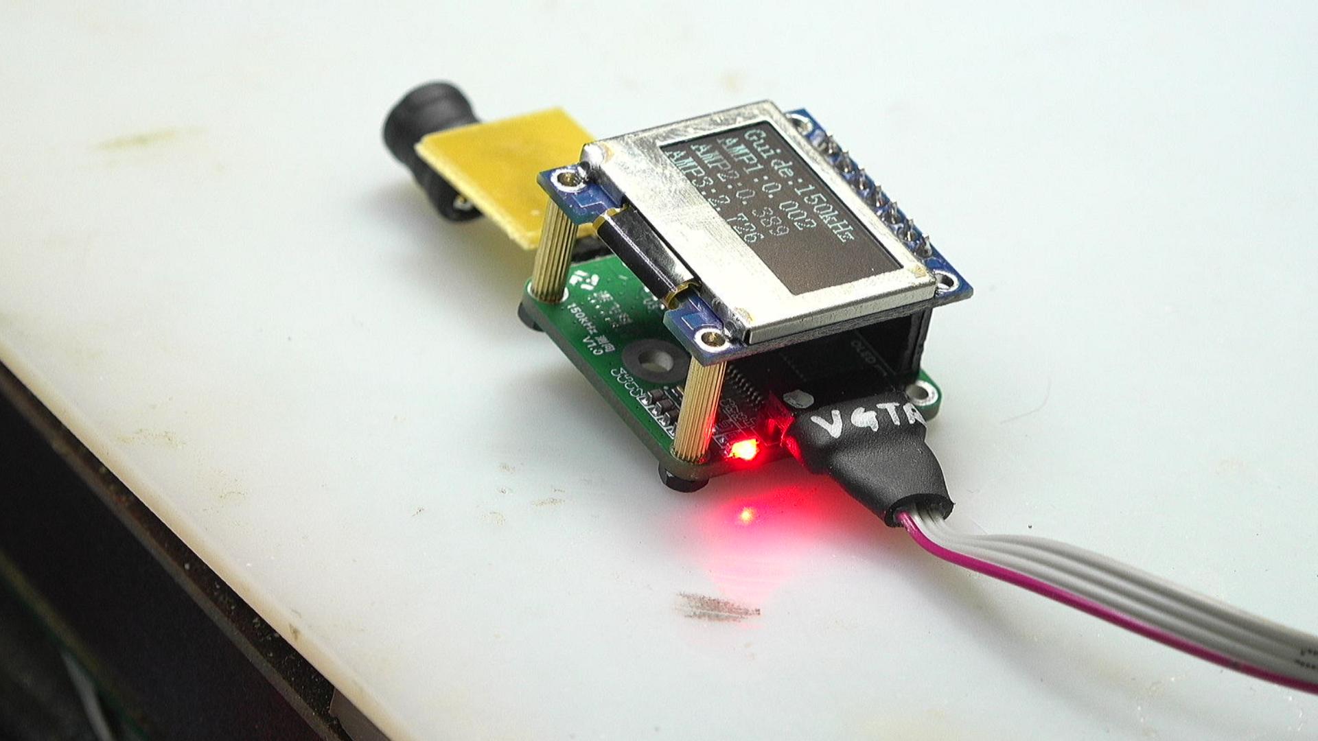
The team adopted a single-sided PCB design for rapid verification. Using the thermal transfer method, the circuit board for testing was produced within one minute. This method is low-cost and fast, and is extremely suitable for early iterations of the project. After connecting this adapter board to the original module, the 5V power supply was connected for data collection.
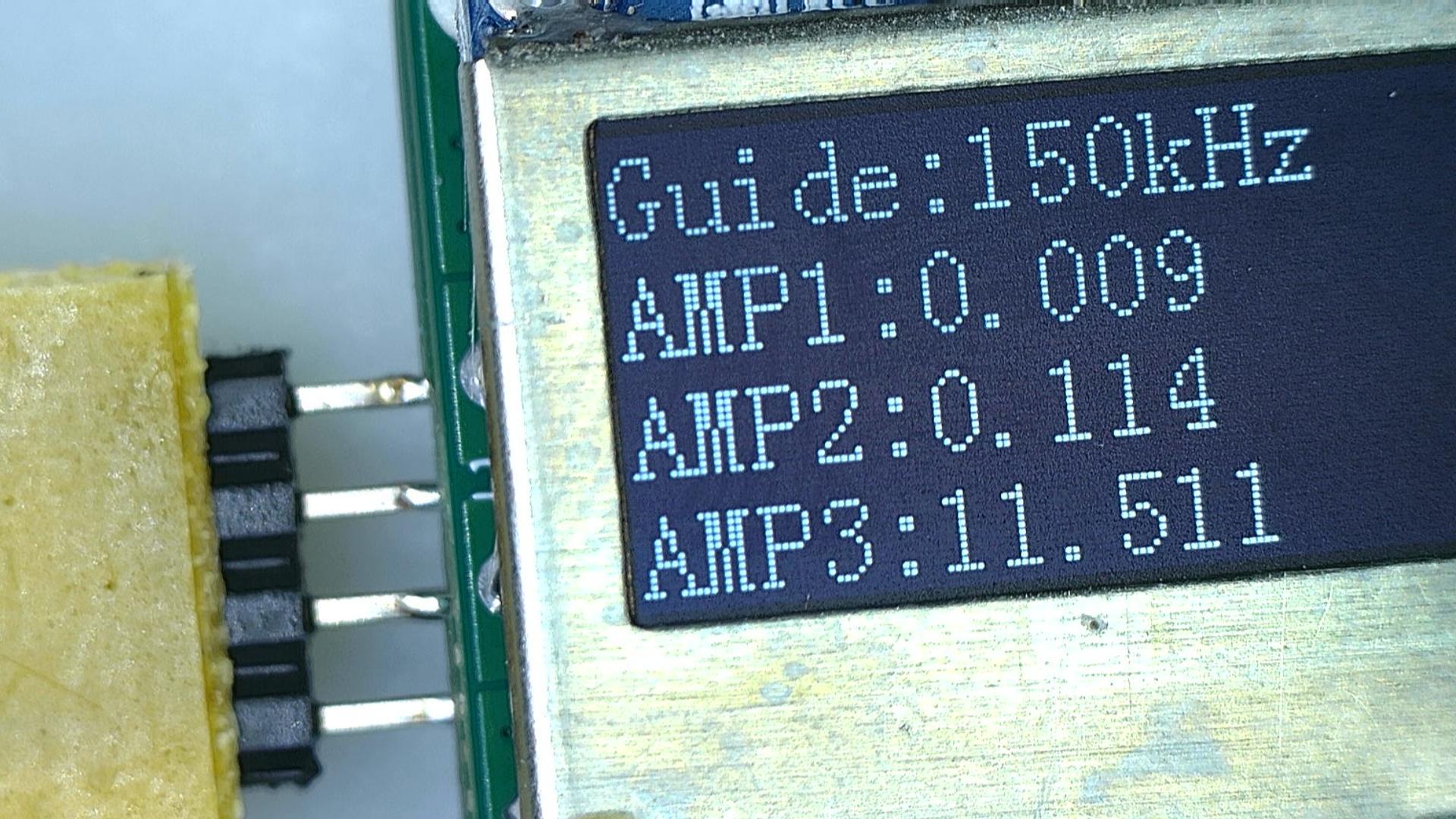
The collected data curve was observed, and the engineer found that the signal fluctuation amplitude had almost no improvement compared with before. This result is of great significance. It directly overturned the original "WiFi high-frequency interference" hypothesis, proving that the source of the noise may not come from the external environment.
Turning to the Exploration of Internal Disturbances
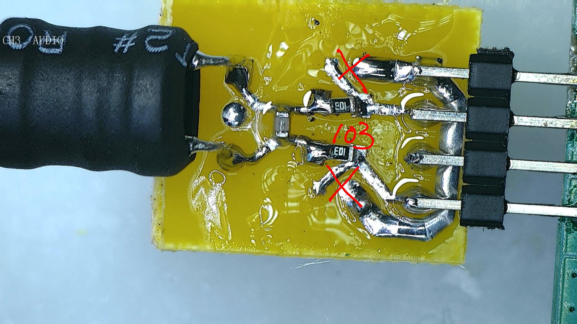
Now that the possibility of external interference has been reduced, attention now turns to the internal direction of the module. The engineer switched the magnetic bead in the filter circuit to a 510-ohm resistor in order to test the noise suppression effect of a pure resistor. Theoretically, resistors have a certain attenuation effect on broadband noise.
The power-on test was performed again, and the collected data still fluctuated extremely violently, showing no obvious improvement. This series of failures shows that the noise source most likely does not enter the signal chain through conventional "conduction", so it is necessary to change the way of troubleshooting.
Key experiments and locking of noise sources
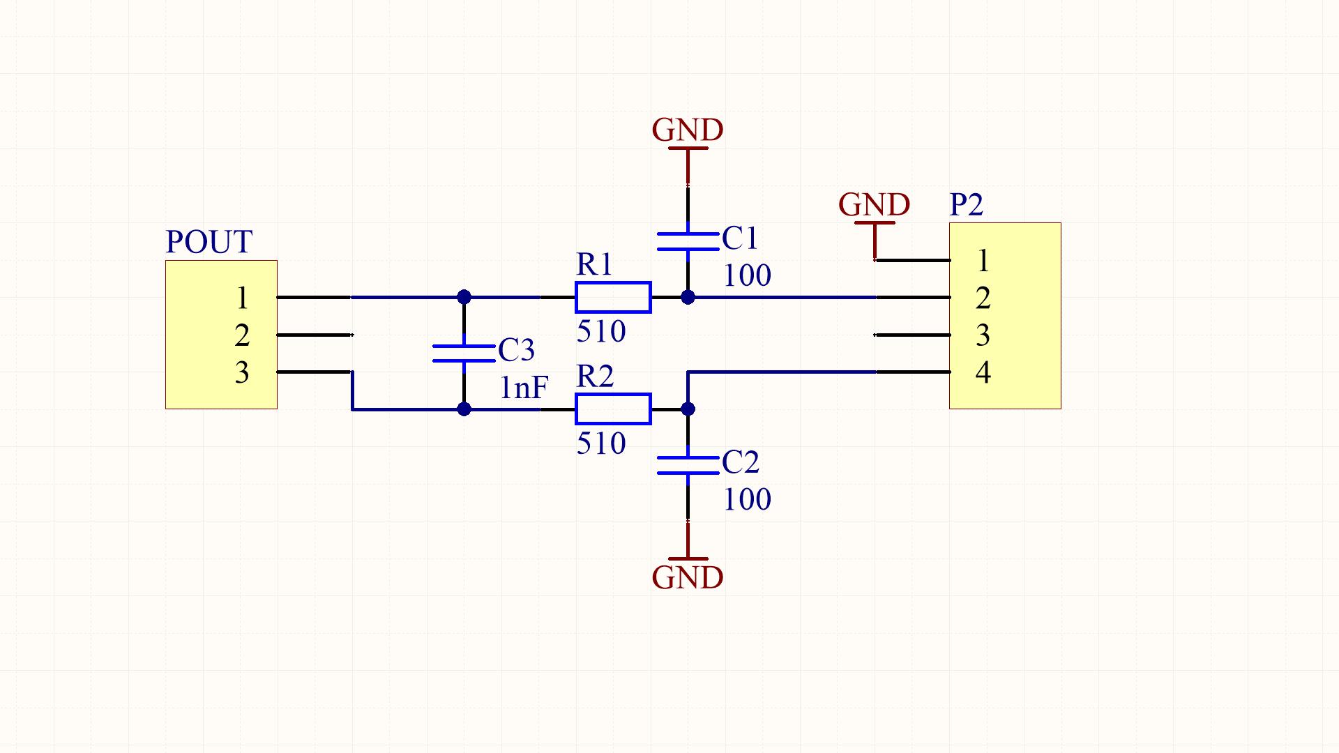
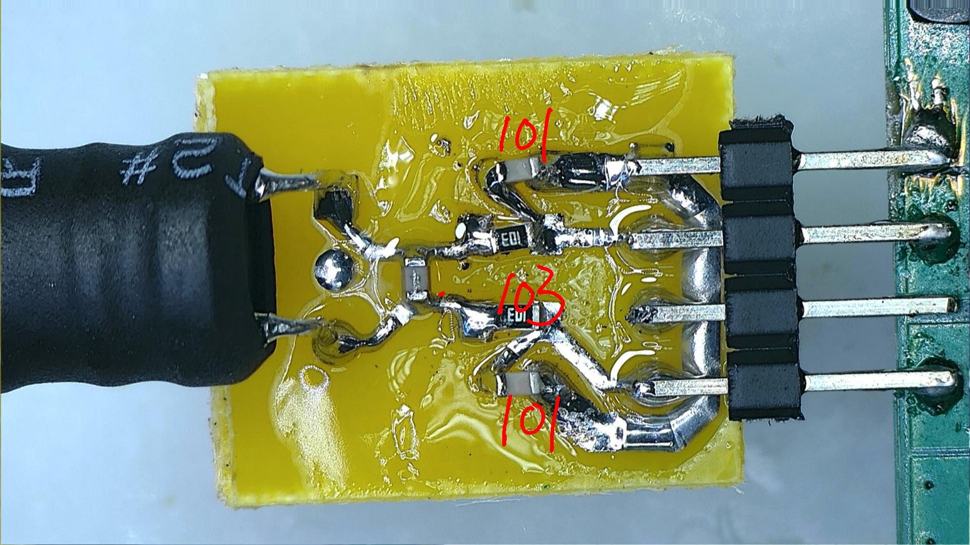
The engineer welded a 1nF capacitor to the ground at the back end of the 510 ohm resistor to form a low-pass filter network. The purpose was actually to ultimately determine the source of interference. This time, the interference burrs on the signal waveform showed a significant reduction, and this change gave a strong hint that the noise entered through some kind of "coupling" path.
The purpose was to verify the role of the capacitor, so the engineers removed the 1nF capacitor, leaving only the series resistor. The corresponding noise immediately resumed. Then, I tried to solder a 0.1nF capacitor, and a similar noise suppression effect was observed. However, the best effect still came from the 1nF capacitor.
Confirmation and solution of interference mechanism
It was also found that although the series resistor was helpful for filtering in the experiment, it also reduced the sensitivity of the antenna. When it was three meters away from the emission source, the maximum acquisition value of the module dropped from 200 to 150, which shows that there is a trade-off between noise suppression and system sensitivity.
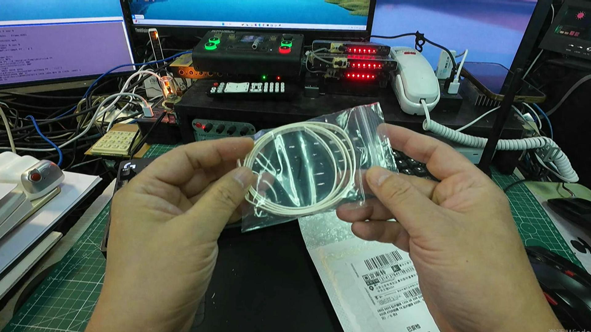
A very convincing experiment is that when the inductor is re-soldered directly to the main circuit board, the noise quickly increases significantly. However, when the inductor is "suspended" with a flat wire 10 cm long, the noise becomes extremely low. This definitely confirms that the interference mainly originates from the parasitic coupling formed by the tight traces inside the module to the receiving inductance.
Final optimization and solution summary
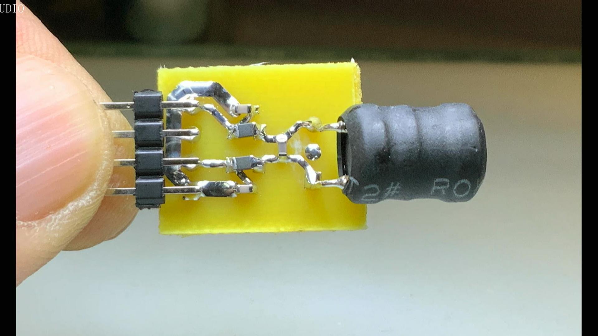
The finalized optimization plan presents a situation where the inductor and the matching resonant capacitor are physically very close together. They are first welded to form an independent sub-module, and then connected to the main circuit board with the help of leads. This can minimize the interference caused by high-frequency digital signals on the motherboard to sensitive analog front-ends.
After removing the local resonance capacitor and soldering it back to the motherboard alone, the noise increased again. Through comparison, it is confirmed that making the inductor and resonant capacitor form a local high-frequency loop is the most effective way to cut off the interference coupling path. The root of the problem is the circuit layout, not the device itself.
During your electronic project development process, have you ever encountered such a tricky situation, that is, the noise seems to come from the outside, but it actually comes from your own circuit layout? Welcome to share your troubleshooting experience and solutions in the comment area. If this article has inspired you, please like it and support it.